 ×
×


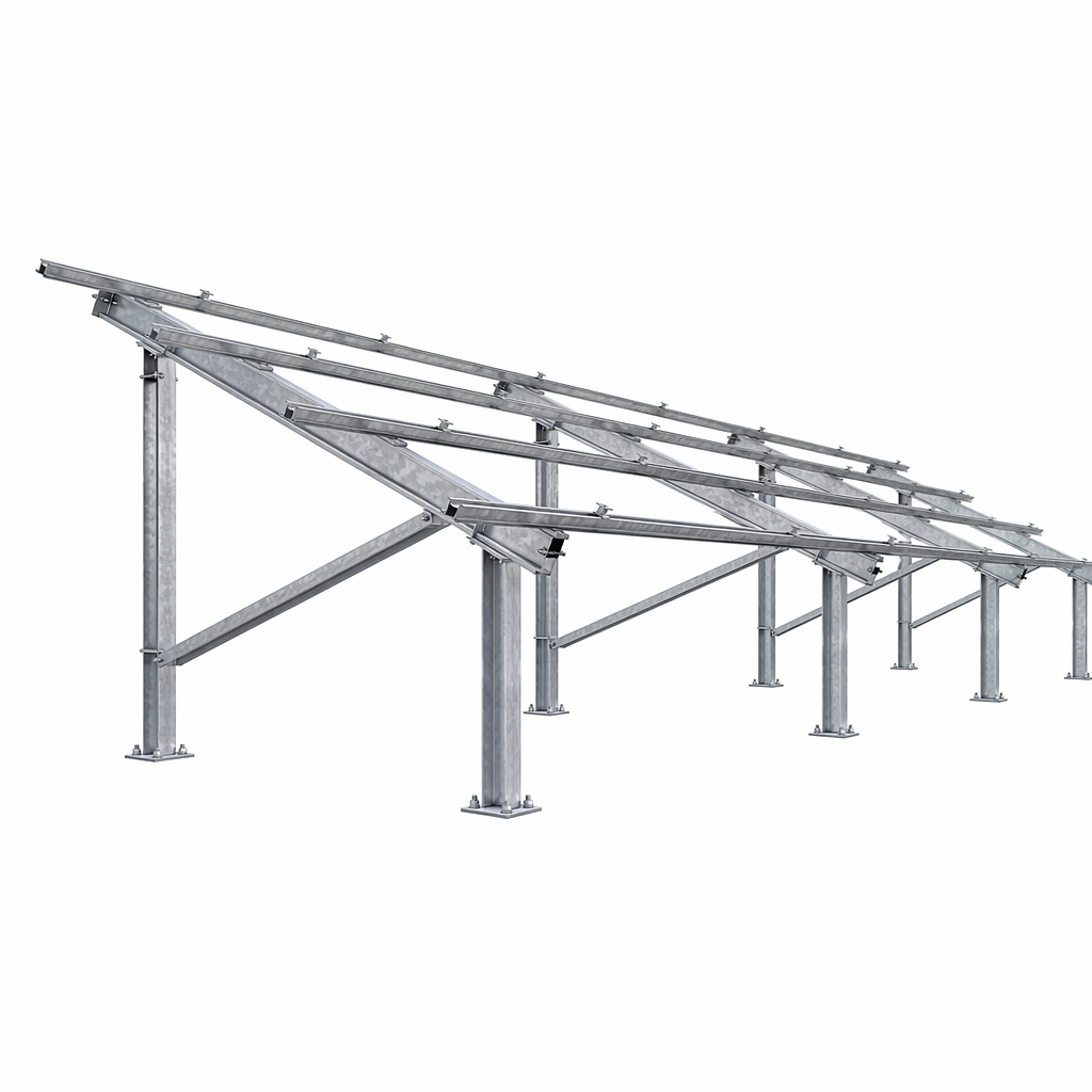
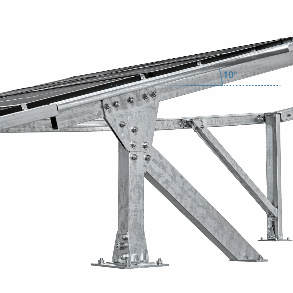
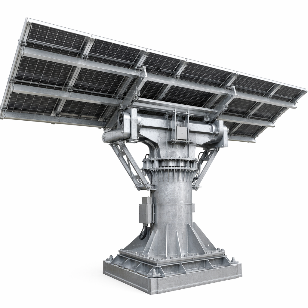
Fixed-Tilt Utility Ground Mount System | Engineered for 1MW–500MW+ Solar Farms Worldwide
Selecting the right ground-mounted solar structure is one of the most consequential decisions in any utility-scale PV project. The mounting system represents approximately 8–12% of total project CAPEX, but a poor choice in structural design, corrosion protection, or foundation strategy can increase your LCOE by 5–15% over the asset lifecycle through higher maintenance costs, premature degradation, and unplanned downtime.
The 10° Fixed-Tilt Utility Ground Mount System is purpose-built to eliminate these risks for project developers, EPC contractors, and independent power producers (IPPs). Manufactured from Q235B / Q355B high-strength structural steel with hot-dip galvanized (HDG) or Zn-Al-Mg coated surface treatment, this system delivers a 25-year design life across the full spectrum of operating environments — from the Sahara to the North Sea coast, from Southeast Asian tropical zones to Andean high-altitude plateaus.
What makes this system different from commodity racking:
Full structural calculation delivered with every order — not just a material list. Our engineering team provides wind load analysis per EN 1991-1-4, snow load verification per EN 1991-1-3, and seismic design per EN 1998 where required, all calibrated to your project's exact GPS coordinates and local design codes.
Three foundation options from one supplier — ground screw, driven pile, and concrete — so you optimize for both geotechnical conditions and construction budget without managing multiple vendors.
Factory pre-assembled sub-arrays — 2×10, 2×12, or 2×14 module arrays arrive with beams, rails, and fasteners pre-fitted, cutting on-site labor by up to 40% and reducing installation errors that cause rework delays.
1500V system-ready — designed for modern high-voltage PV architectures that reduce BOS cost per watt.
Whether you are tendering a 50MW government solar park in West Africa, building a 200MW IPP project in the Middle East, or expanding a commercial rooftop-to-ground hybrid installation in Europe, this system provides the structural certainty your financial model demands.
1. High Structural Strength for Long-Span, High-Density Arrays
Utility-scale projects require fewer rows with higher module density per row to minimize land use and civil works. Our system uses Q355B low-alloy structural steel for primary load-bearing members, offering 40% higher yield strength than standard Q235B while maintaining excellent weldability and cold-forming characteristics.
Metric |
Q235B Standard |
Q355B Upgrade |
Yield strength |
235 MPa |
355 MPa |
Tensile strength |
370–500 MPa |
470–630 MPa |
Recommended span |
Up to 30m per row |
Up to 45m per row |
Post spacing |
Every 3–4m |
Every 4–6m |
For projects in regions with challenging geotechnical conditions — expansive clay, loose sand, high water table — the Q355B option reduces the number of foundation points required, directly lowering piling and civil works cost.
2. Multi-Tier Corrosion Protection Engineered for Your Site
Corrosion is the silent killer of solar asset returns. We map your project's ISO 9223 atmospheric corrosivity category to the correct surface treatment:
Corrosivity Category |
Typical Site Conditions |
Recommended Treatment |
C2 (Low) |
Rural inland, low humidity |
HDG ≥ 55μm (ISO 1461) |
C3 (Medium) |
Urban/industrial inland |
HDG ≥ 70μm + optional topcoat |
C4 (High) |
Coastal 1–10km, tropical |
HDG ≥ 85μm or Zn-Al-Mg |
C5 (Very High) |
Offshore <1km, heavy industry |
Zn-Al-Mg alloy coating + HDG ≥ 100μm |
Why Zn-Al-Mg matters: Unlike standard HDG, Zn-Al-Mg coatings form a dense, self-healing patina that actively seals cut edges and scratches — the most common failure points in field-assembled steel structures. Independent salt-spray testing (ASTM B117) shows Zn-Al-Mg coated fasteners surviving 3,000+ hours without red rust, compared to 1,000–1,500 hours for standard HDG.
3. Faster Installation = Earlier Grid Connection = Earlier Revenue
Every week of delayed commissioning costs a 50MW plant approximately \$15,000–\$25,000 in lost revenue at typical PPA rates. Our pre-assembled module approach targets the single largest driver of on-site schedule risk: mechanical assembly labor.
Pre-assembled sub-arrays with pre-fitted rails and fasteners
Color-coded, batch-packed hardware per array zone
Tool-less clip connections for rail-to-beam joints (patented design)
Standardized post-to-beam brackets — one bracket type for all connections
Real-world result from a 30MW project in Burkina Faso: the EPC contractor reported 4.2 MW/day peak installation rate using 6 crews, compared to 2.8 MW/day for conventional bolt-together systems — a 50% productivity gain.
4. Three Foundation Systems, One Engineering Partner
Foundation Type |
Best For |
Key Advantage |
Ground Screw |
Sand, clay, soft soil, remote sites |
No concrete, no curing time, 60% faster |
Driven Pile |
Firm soil, large flat sites |
Lowest cost per foundation point at scale |
Concrete |
Rocky terrain, high wind zones |
Maximum stability, complex geology |
For a typical 50MW site with mixed soil conditions, a hybrid approach (ground screws for 70% of the site, driven piles for 30%) can reduce total foundation cost by 15–20% versus concrete-only design.
5. Engineered for Extreme Environmental Loads
Load Type |
Design Capability |
Applicable Standard |
Wind load |
Up to 50 m/s (180 km/h, Cat 3 cyclone) |
EN 1991-1-4 / ASCE 7 |
Snow load |
Up to 5,400 Pa |
EN 1991-1-3 / JIS C 8955 |
Seismic |
Response spectrum analysis available |
EN 1998 / IBC |
Temperature |
−40°C to +60°C operational range |
Material testing certified |
Input Collection (Day 0): Project GPS coordinates, module datasheet, geotechnical report, target DC capacity
Load Calculation (Day 1–2): Design wind speed, terrain category, topography factor, snow load per governing code. For regions without codified wind maps, we use ERA5 reanalysis data (40-year hourly records)
Structural Modeling (Day 2–3): SAP2000 / RFEM modeling including post buckling, rail/beam bending moments, connection design, foundation capacity verification
Optimization Loop (Day 3–4): Material takeoff optimization — adjusting post spacing, sections, embedment depth — to minimize total installed cost while maintaining ≥1.5 safety factor
Deliverables (Day 4–5): Structural calculation report (PDF, stamped), GA drawings (DWG + PDF), foundation layout with GPS coordinates, detailed BOM with pricing, installation manual
Parameter |
Specification |
Structure Type |
Fixed-Tilt Ground Mount |
Tilt Angle |
10° (fixed); 15–30° adjustable series also available |
Module Orientation |
Portrait (2P); Landscape options available |
Module Layout |
2×10 / 2×12 / 2×14 (custom on request) |
Primary Material |
Q235B / Q355B structural steel (GB/T 1591) |
Surface Treatment |
HDG (ISO 1461) / Zn-Al-Mg alloy coating |
Corrosion Protection |
C3–C5 (ISO 12944) |
Design Wind Load |
Up to 50 m/s |
Design Snow Load |
Up to 5,400 Pa |
System Voltage |
1000V / 1500V DC |
Foundation Types |
Ground Screw / Driven Pile / Concrete |
Design Life |
25 years |
Structural Warranty |
25 years |
Design Standards |
EN 1990–1998, ASCE 7, AS/NZS 1170, JIS C 8955 |
Module Compatibility |
Longi, JA Solar, Jinko, Trina, Canadian Solar, Risen, all major framed modules |
Utility-Scale Solar Farms (10MW–500MW+)
IPP & Government Tender Projects
Agricultural PV (Agrivoltaics)
Desert Solar Stations (MENA)
Coastal & Island Projects
Mountain & High-Altitude Sites
Mining & Brownfield Redevelopment
Industrial Park Rooftop-Ground Hybrid
Ground Screw Foundation: Ø68–114mm, 1200–2500mm length, 20–50kN pull-out, 150–250 screws/day per machine. No concrete, reusable.
Driven Pile Foundation: C100–C150 channel sections, 1.2–2.5m embedment, 300–500 piles/day per machine. Lowest per-pile cost at scale.
Concrete Foundation: Cast-in-place or precast. EN 1992 / ACI 318 compliant. For rocky terrain and high-wind zones.
Step |
Activity |
Duration (50MW, 6 crews) |
Quality Check |
1 |
Site survey & layout staking |
2–3 days |
GPS verification of foundation coordinates |
2 |
Foundation installation |
15–25 days |
Pull-out test (1 per 200 foundations) |
3 |
Post installation |
5–8 days |
Post top elevation ±5mm across row |
4 |
Main beam assembly |
8–12 days |
Bracket torque verification (10% sample) |
5 |
Rail installation |
10–15 days |
Rail straightness; grounding continuity |
6 |
Module mounting |
15–20 days |
Module alignment; string voltage check |
7 |
Final inspection |
2–3 days |
Complete torque audit; as-built vs design |
Total mechanical installation: approximately 45–55 working days for 50MW.
30MW Burkina Faso, West Africa: Q355B with HDG ≥85μm (C4). Ground screw foundation (Ø76mm, 1600mm) eliminated concrete logistics. 2×14 layout. 52 working days mechanical completion. 3+ years operation with zero structural issues.
100MW Al Dhafra, UAE: Zn-Al-Mg alloy coating (C5 equivalent). Driven pile 2.5m embedment for sabkha conditions. 2×12 layout, 10° tilt. Installation peak rate 6.1 MW/day. Annual O&M structural cost 40% below desert benchmark.
20MW Agrivoltaic, Extremadura, Spain: Elevated structure, 1.5m min ground clearance for sheep grazing. Adjustable-height posts (1.5–2.2m) for 3–5% grade terrain. 2×10 layout. Recognized in EU Agrivoltaics Best Practice Report 2024.
Region |
Design Code |
Wind Code |
Europe / Africa / Middle East |
EN 1993-1-1 |
EN 1991-1-4 |
North America |
AISC 360 |
ASCE 7-22 |
Australia / New Zealand |
AS/NZS 4600 |
AS/NZS 1170.2 |
Japan |
JIS C 8955 |
JIS C 8955 |
Factory Certifications: ISO 9001:2015, ISO 14001:2015, ISO 45001:2018, EN 1090-1 EXC2 (CE marking eligible)
Capability |
What It Means for Your Project |
20+ Years Steel Structure Manufacturing |
Optimized section design — less steel per MW |
Complete In-House Production Line |
No subcontractor quality risk |
ISO-Certified Factory |
EN 1090-1 EXC2 compliant |
Professional Engineering Team |
15+ structural engineers, SAP2000/RFEM in-house |
Worldwide Project Experience |
30+ countries across 5 continents |
Strict Quality Control |
MTC verification, in-process inspection, pre-dispatch audit |
Fast Delivery |
4–6 weeks standard; 2–3 weeks express available |
Full Lifecycle Technical Support |
From pre-bid engineering to year-5 structural inspection |
Q1. Can you design the mounting structure according to our specific project?
Yes. Every order includes project-specific structural calculations, layout drawings, and BOM. Complete engineering package delivered within 5 working days of receiving your project data.
Q2. Which international structural standards do you comply with?
We design to EN 1993, ASCE 7, AS/NZS 1170, JIS C 8955, and other national standards. Factory holds EN 1090-1 EXC2 certification for CE-marked structural components.
Q3. What foundation option should I choose?
Depends on soil bearing capacity, groundwater, corrosivity, and budget. We recommend a geotechnical survey first. Our team provides a foundation comparison report covering cost, schedule, and risk. Hybrid approach (screw + pile) often optimal.
Q4. What is the design life and warranty?
25-year design life. 25-year structural warranty for HDG and Zn-Al-Mg products. Actual service life in C3–C4 environments typically exceeds 30 years.
Q5. Do you provide wind tunnel testing?
Code-based calculations for standard projects. Wind tunnel testing through partner labs for 100MW or complex-topography sites. CFD analysis available for sites near buildings or terrain features.
Q6. What is the minimum order quantity?
500kW (approximately one 40ft container) for first-time evaluation. Flexible batch shipments for repeat EPC clients.
Q7. Can you supply installation tools?
Torque wrenches, hydraulic pile drivers, and ground screw adapters available on rental or purchase basis. On-site installation supervision available for large projects.
# |
Section |
Recommendation |
Format |
1 |
Hero |
Drone shot of completed utility-scale solar farm |
1920×750px |
2 |
Overview |
3D exploded-view rendering with labeled components |
1200×800px |
3 |
Structural Strength |
Q235B vs Q355B cross-section comparison diagram |
800×600px |
4 |
Corrosion |
Macro photo: HDG vs Zn-Al-Mg surface comparison |
600×400px |
5 |
Installation |
Time-lapse sequence: bare land → modules |
1000×400px |
6 |
Foundations |
Three-panel: ground screw / driven pile / concrete cross-section |
1200×500px |
7 |
Engineering |
5-step process flow diagram |
1000×500px |
8 |
Case Burkina Faso |
On-site installation photo |
800×600px |
9 |
Case UAE |
Aerial: Al Dhafra solar park |
800×600px |
10 |
Case Spain |
Sheep grazing under elevated PV array |
800×600px |
11 |
Installation Guide |
7-step illustrated guide |
1200×3000px |
12 |
Standards |
Certification badge grid |
800×200px |
13 |
Factory |
Production line / HDG bath / QC station |
1200×700px |
14 |
Team |
Engineering team at work |
800×500px |
15 |
CTA |
Product render with contact form overlay |
1920×500px |
Primary: fixed tilt ground mount system, utility-scale solar mounting structure, solar ground mounting system, ground-mounted PV racking system
Secondary: solar farm mounting structure, fixed tilt solar racking, utility solar mounting manufacturer, Q355B solar ground mount, pre-assembled solar mounting system, solar foundation ground screw
Long-Tail: ground mount solar structure for 50MW project, EN 1993 solar mounting structure manufacturer, 25-year warranty solar ground mount, solar mounting system BOM quotation

 EN
EN