 ×
×


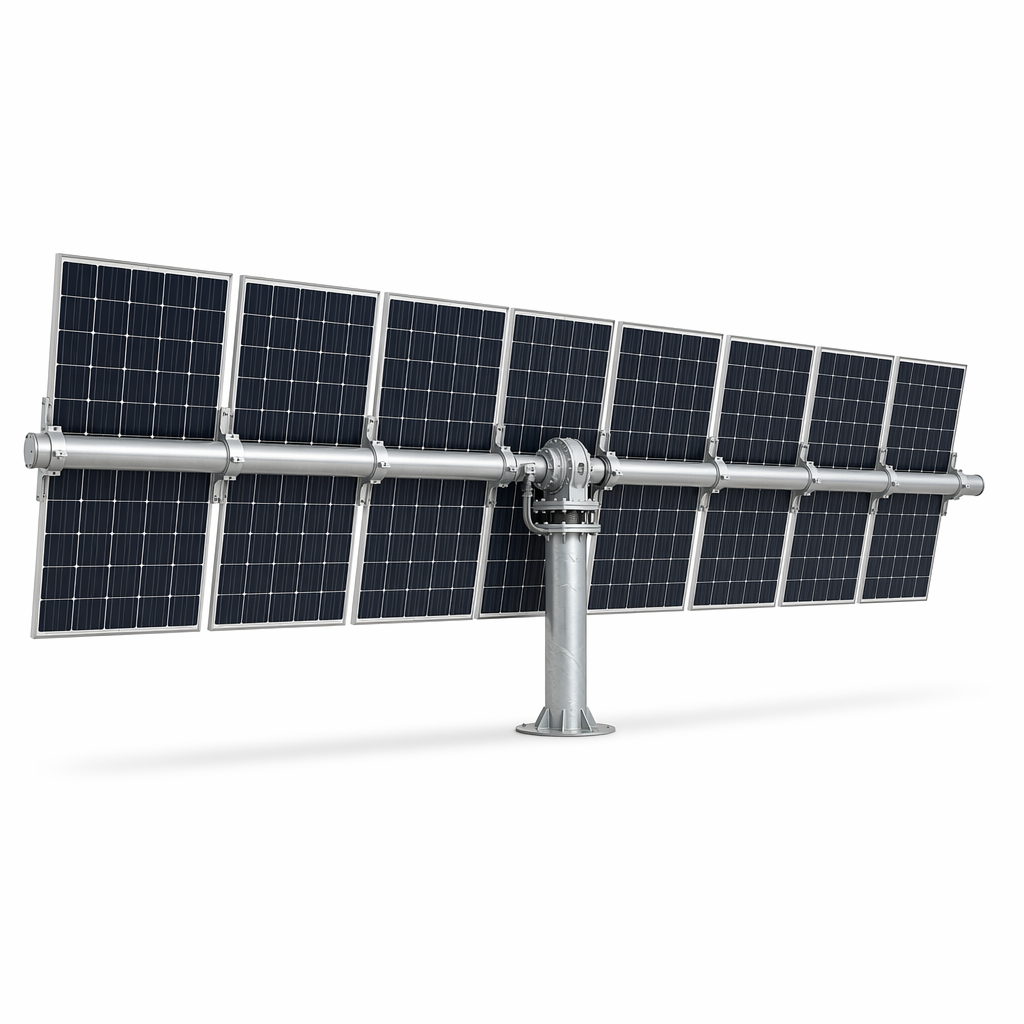
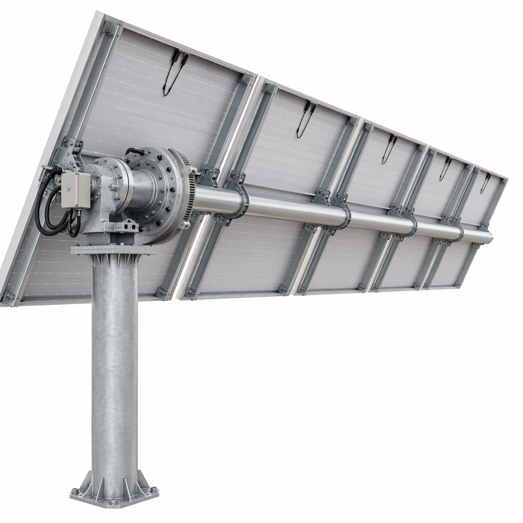
1P Horizontal Single-Axis Tracking System | +25% Energy Yield for Flat-Terrain Utility PV Farms up to 100MW+
The 1P (One-in-Portrait) Horizontal Single-Axis Tracking System is the industry-standard tracker architecture for utility-scale PV plants on flat to gently rolling terrain. By rotating each row of modules east-to-west throughout the day to follow the sun's azimuth, this system captures 20–28% more annual energy than an equivalent fixed-tilt installation — a gain that directly improves project IRR, reduces LCOE, and strengthens PPA competitiveness.
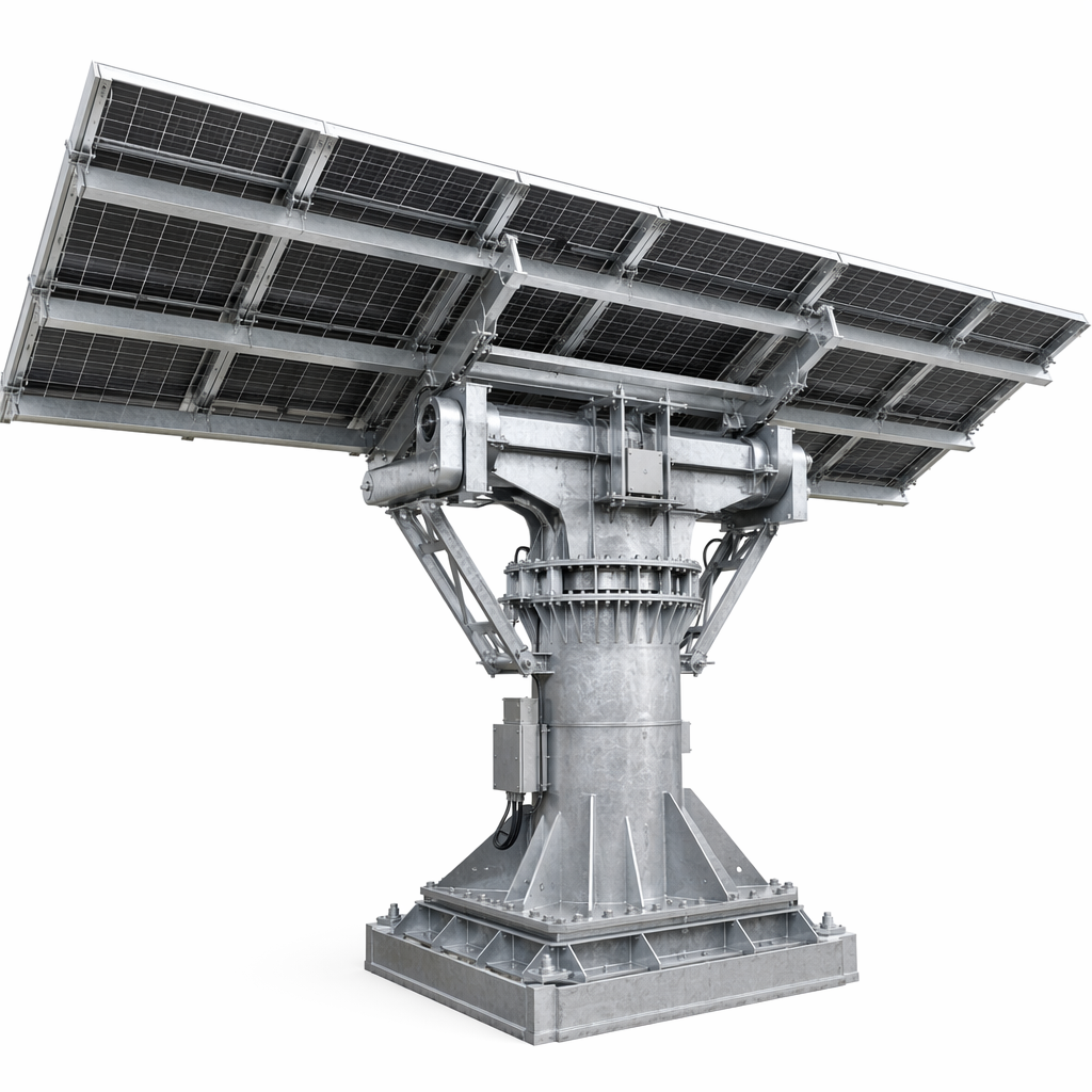
This system is designed for scale. Each tracker row accommodates 60–120 modules in 1P configuration (modules in portrait orientation on a single torque tube), driven by a centralized slew-drive motor at the row center. The system's 2P variant doubles module count per row to 120+ modules for ultra-high-density layouts.
Key engineering features:
Slew-drive actuator (not linear actuator/push-rod): The slew drive provides continuous 360° rotation capability with high torque density and zero backlash, suitable for the high-cycle fatigue environment of daily solar tracking (9,000+ cycles over 25 years)
±0.5° tracking accuracy: Closed-loop control via inclinometer feedback, not open-loop time-based positioning that drifts without correction
Astronomical algorithm + backtracking: The controller calculates sun position from GPS coordinates and date/time, with backtracking logic that flattens rows during low sun angles to eliminate inter-row shading
Q355B galvanized steel torque tube with C4 corrosion protection: Sized per row length and local wind load for torsional stiffness that prevents row twist and module misalignment
Metric |
Fixed Tilt (10°) |
1P Single-Axis Tracker |
Annual yield gain |
— |
+20% to +28% |
Capacity factor improvement |
— |
+3 to +5 percentage points |
LCOE reduction |
— |
8–15% (vs fixed tilt equivalent) |
Land use efficiency (GCR) |
0.35–0.45 |
0.35–0.50 |
Added CAPEX vs fixed |
— |
\$0.04–0.07/Wdc |
Parameter |
1P Horizontal Single-Axis |
2P Variant |
Tracking Axis |
Horizontal (E-W rotation) |
Horizontal (E-W rotation) |
Module Orientation |
Portrait (1P) |
Portrait, 2 rows per torque tube (2P) |
Modules per Row |
60–90 |
90–120 |
Tracking Range |
±55° from horizontal |
±55° from horizontal |
Tracking Accuracy |
±0.5° |
±0.5° |
Drive Type |
Slew drive (central) |
Slew drive (central) |
Control Method |
Astronomical algorithm + GPS + inclinometer feedback |
Same |
Backtracking |
Yes (inter-row shading elimination) |
Yes |
Wind Stow |
Auto-stow at 25 m/s (running) |
Auto-stow at 25 m/s |
Survival Wind Speed |
42 m/s (stowed position) |
42 m/s |
Torque Tube |
Q355B HDG steel, Ø168–219mm |
Q355B HDG steel, Ø219–273mm |
Foundation |
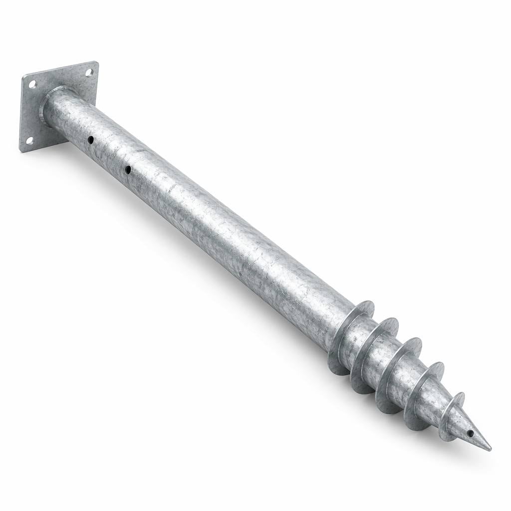
Driven pile / Ground screw |
Driven pile / Ground screw |
Design Life |
25 years structure / 5 years drive |
Same |
Structure Warranty |
20 years |
20 years |
Drive Warranty |
5 years |
5 years |
Flat-terrain utility PV farms (10MW)
High-DNI regions (MENA, South Africa, Chile, Australia, US Southwest, India)
Large-scale IPP and government tender projects
Sites where land cost justifies higher GCR
Site topography analysis: Maximum N-S slope grade verified (<5% for standard design; >5% requires terraced row adaptation)
Wind tunnel load coefficients: Cp values for the specific module geometry at all tracker angles, per wind tunnel testing or CFD analysis
Torque tube sizing: Torsional stiffness calculation to limit row twist to <1° under design wind, preventing module misalignment and glass stress
Foundation design: Lateral load and overturning moment verification per EN 1997-1, accounting for the dynamic load amplification from tracker movement
Row spacing optimization: Backtracking algorithm simulation across the full year to determine minimum row pitch without shading loss
Step |
Activity |
Duration Reference |
1 |
Foundation (driven pile) |
3–5 minutes per pile |
2 |
Bearing assembly installation |
Pre-assembled bearing-saddle units placed on piles |
3 |
Torque tube assembly |
Segments bolted together on-site, lifted onto bearings |
4 |
Drive motor installation |
Slew drive mounted at row center |
5 |
Module rail installation |
Rails attached to torque tube purlin brackets |
6 |
Module mounting |
Standard module clamping to rails |
7 |
Electrical & control |
Motor wiring, controller commissioning, tracking test cycle |
Challenge: Flat semi-desert terrain with high DNI (2,200+ kWh/m²/year). Project requirement for 25% yield gain over fixed tilt to meet PPA financial model. Wind gusts to 35 m/s during summer thunderstorm season.
Solution: 1P horizontal single-axis tracker, Ø219mm torque tube, slew drive, astronomical algorithm with GPS syncing and backtracking enabled. Q355B HDG steel, C4 coating. Driven pile foundation. 90 modules per row, 2×45 portrait. Auto-stow wind protection triggered at 25 m/s.
Result: Measured 26.4% annual yield gain over fixed-10° benchmark installation at same site. Zero row-to-row shading losses confirmed by on-site pyranometer measurement. Wind stow events averaged 12 per year; zero structural or drive damage after 3 years of operation.
Q. What is the payback period for tracker vs fixed tilt?
For a high-DNI site (2,000+ kWh/m²/year), the tracker premium (\$0.04–0.07/Wdc) typically pays back in 3–5 years through increased energy revenue. This is heavily site-dependent — at lower DNI sites (<1,500 kWh/m²/year), the payback extends to 6–8 years, and fixed tilt may be more appropriate.
Q. How does backtracking work and why is it necessary?
During early morning and late afternoon when the sun is low, the front row would cast a shadow on the row behind it. Backtracking flattens all rows to a near-horizontal angle during these periods, sacrificing some tracking gain to eliminate shading. The net effect is a small energy loss at dawn/dusk but prevents 5–8% shading-related losses that would otherwise occur.
Q. What maintenance does the drive system require?
Slew drives are sealed, grease-lubricated units requiring inspection every 2 years and grease replenishment as needed. The drive motor is an IP65-rated unit with brushless DC design for long service life. The 5-year drive warranty covers motor, gearbox, and controller electronics.
# |
Section |
Recommendation |
Format |
1 |
Hero |
Aerial drone shot of tracker rows at mid-morning angle |
1920×750px |
2 |
Mechanism |
Close-up: slew drive mounted on torque tube with pile foundation |
800×600px |
3 |
Yield comparison |
Bar chart: monthly yield fixed vs tracker |
800×500px |
4 |
Backtracking |
Diagram: row angles at 7am / 10am / 1pm / 4pm / 6pm |
1000×400px |
5 |
Installation |
Time-lapse of tracker row assembly |
800×500px |
6 |
Case South Africa |
Completed 80MW tracker field |
1000×600px |
Primary: single axis solar tracker, 1P horizontal tracker, solar tracking system utility scale, PV tracker manufacturer
Secondary: horizontal single axis tracker 25% yield gain, solar tracker slew drive, backtracking solar tracker, utility PV tracking system

 EN
EN