 ×
×


Precision Dual-Axis Solar Tracker | ±0.1° Accuracy for PV Module Testing, Solar Research Stations, and Calibration Laboratories
Solar R&D demands tracking accuracy that commercial power-plant trackers do not provide. When you are measuring a PV module's I-V curve to 0.1% precision for IEC 61853 energy rating, comparing bifacial module performance under controlled conditions, or calibrating a pyranometer against a reference cell, tracking error becomes measurement error.
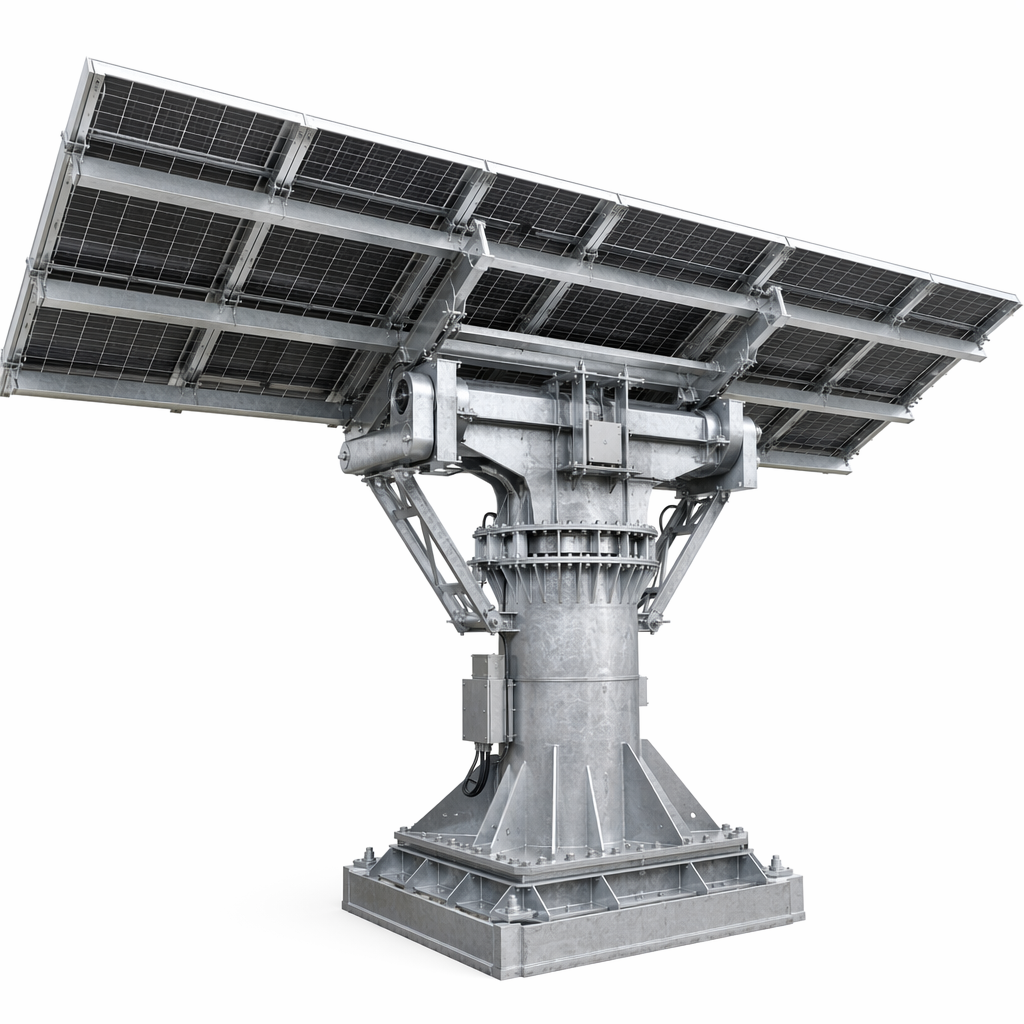
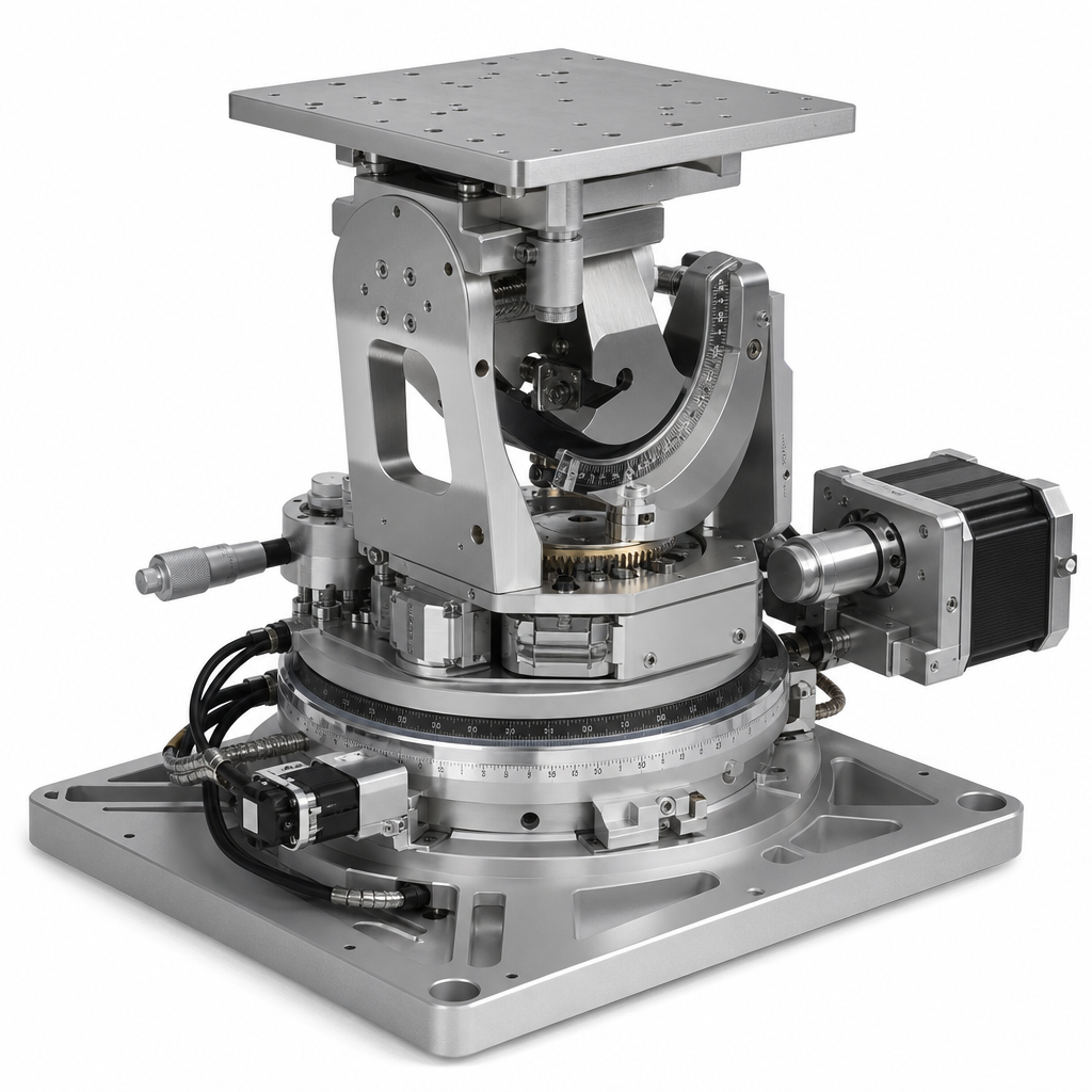
The Precision Dual-Axis Tracking System achieves ±0.1° tracking accuracy — five times tighter than commercial tracker specifications — using a combination of:
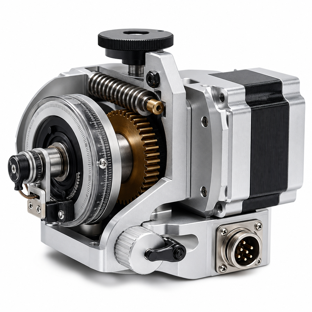
High-resolution optical encoders (not inclinometers) on both axes, providing absolute angular position to 0.01° resolution
Closed-loop sun sensor with quadrant photodiode array that actively centers on the solar disk, correcting for atmospheric refraction, mount deflection, and thermal expansion in real time
Rigid, low-deflection structure: The tracker pedestal and torque assembly use oversized steel sections to limit structural deflection under wind load to <0.05° — because encoder accuracy is meaningless if the structure bends
Temperature-stabilized foundation: An isolated concrete pier foundation decoupled from adjacent building slabs to prevent thermal expansion-induced tilt
This is a scientific instrument, not a power-plant tracker. Typical deployments include national renewable energy laboratories, university solar research centers, module manufacturer QA/QC test fields, and meteorological agency solar resource measurement stations.
Parameter |
Specification |
Tracking Type |
Full Dual-Axis |
Azimuth Range |
0°–360° |
Elevation Range |
0°–90° |
Tracking Accuracy |
±0.1° (both axes, verified) |
Position Resolution |
0.01° (optical encoder) |
Tracking Method |
Astronomical algorithm + closed-loop sun sensor + optical encoder feedback |
Drive Type |
Precision worm-gear slew drive with zero-backlash preload |
Module Capacity |
4–12 modules (depending on module size and wind zone) |
Operating Wind Speed |
Up to 15 m/s (for ±0.1° accuracy maintained) |
Survival Wind Speed |
50 m/s (stowed) |
Structural Material |
Q355B HDG steel + stainless steel fasteners |
Foundation |
Isolated reinforced concrete pier |
Data Output |
Real-time tracking angle (Modbus TCP), 1 Hz logging |
Structure Warranty |
20 years |
Drive Warranty |
5 years |
PV module I-V curve measurement and energy rating (IEC 61853)
Bifacial module performance comparison testing
Pyranometer and reference cell calibration
National solar resource measurement networks
University and government solar research facilities
Module manufacturer R&D and QA/QC outdoor test fields
Challenge: Facility required a tracker capable of maintaining ±0.1° accuracy across full annual temperature range (−15°C to +40°C) for reference module calibration traceable to international standards. Previous commercial tracker installation showed 0.3–0.5° cyclic error due to thermal expansion of the steel pedestal.
Solution: Precision dual-axis system with optical encoders, sun sensor closed-loop correction, temperature-stabilized foundation, and oversized pedestal section to minimize thermal bow. Modbus TCP data output integrated with the facility's existing data acquisition system for 1-second-resolution angle logging.
Result: ±0.08° RMS tracking accuracy verified by independent theodolite measurement over a 12-month period. Zero thermal-expansion-induced cyclic error. System has operated for 4 years with annual recalibration only.
Q. How is ±0.1° accuracy verified?
During commissioning, a survey-grade theodolite is used to independently measure tracker position at multiple points throughout the day. The RMS error between commanded and measured position is calculated over a full tracking day. This verification is repeated annually or after any significant maintenance event.
Q. Can this system be used for outdoor PV module accelerated aging testing?
Yes. The tracker can be programmed to follow custom tracking profiles — including fixed angles, accelerated sun-tracking paths, or simulated cloudy-day patterns — in addition to standard solar tracking. This flexibility supports a wide range of research protocols.
# |
Section |
Recommendation |
Format |
1 |
Hero |
Precision tracker with test modules, research facility context |
1920×750px |
2 |
Encoder detail |
Close-up: optical encoder mounted on drive shaft |
600×400px |
3 |
Sun sensor |
Quadrant photodiode sun sensor assembly |
600×400px |
4 |
Control interface |
Screenshot: tracking angle display with ±0.1° error band |
800×500px |
Primary: precision solar tracker ±0.1 degree, dual axis tracker PV testing, solar research tracker, PV module calibration tracker
Secondary: high accuracy sun tracking system, IEC 61853 solar tracker, solar reference cell tracker, laboratory grade PV tracker

 EN
EN